
Stage 13 · Plan the routes before hiding them
Planning your campervan electrics and cable routes
Start with what you want to use, where you will use it and how you will recharge. You do not need to understand every electrical calculation to make a useful plan. A clear list, sensible equipment positions and well-recorded routes give your installer something practical to work from.

1. List the things you actually want to use
Begin with an ordinary day in the van. Charging two phones, running a fridge, switching on a water pump and reading in bed is a different starting point from using an induction hob, microwave or electric water heater. Tell the installer what matters to you before choosing the battery.
Write down the actual product if you have selected it. Otherwise, describe the job it needs to do and mark it as undecided. A description such as “laptop charging at the table” is more useful at this stage than buying cable because it looks thick enough.
Include things you may forget: ventilation fans, heating controls, ignition, monitors, router, step lights and any toilet or water-system electronics.

| Write down | Useful detail |
|---|---|
| What you will use | Product/model if known, or the job it needs to do. |
| Where you will use it | Kitchen, bed, table, garage or outside connection point. |
| How you use it | Occasionally, throughout the day, overnight or at the same time as another large load. |
| How you expect to recharge | Driving, solar, optional mains hook-up or a combination. |
| What may change | Likely future equipment, with enough detail to make a meaningful provision for it. |
The planner’s beginner estimates can help you choose a starting budget and compare options. Keep estimates separate from a confirmed system design. Do not treat an equipment shopping list, a matching connector or a “Check my setup” review as approval of the wiring.
Ask for the design to account for the way you really use the van, including simultaneous loads, recharging opportunities and the conditions you expect. You can keep the everyday choices simple while the installer handles the calculations.
Understand the jobs of the main parts
You do not need to memorise a circuit diagram to understand the outline. Think of the system as storage, ways of charging it, ways of distributing the supply and the things that consume it. Protection and isolation are designed around all of those parts.
| Part | Its role in the plan |
|---|---|
| Leisure battery | Stores energy for the living area; choose it with the intended loads, charging equipment and installation conditions. |
| DC distribution | Supplies suitable low-voltage equipment through the designed circuits and protection. |
| Charging equipment | May include vehicle charging, a solar controller and/or a mains charger, as appropriate to the actual system. |
| Inverter, if required | Provides AC power from the battery for suitable loads. It adds its own capacity, installation and protection requirements. |
| Mains installation, if included | Needs a complete arrangement for inlet, distribution, protection, earthing and any changeover between supplies. |
| Monitoring and controls | Help you operate and understand the system; they do not replace electrical protection or inspection. |
A leisure system commonly includes nominal 12 V DC equipment, while UK mains appliances normally use 230 V AC. Check each actual device and system voltage rather than assuming every camper accessory is interchangeable. Low-voltage batteries can still supply enough fault current to cause severe heating and fire.
A portable power station is another possible approach, with its own operating and charging instructions. It is not permission to connect its AC output to a fixed van installation through improvised leads. Have any fixed integration designed for the actual product; never backfeed a supply through a socket.
2. Choose a protected battery location
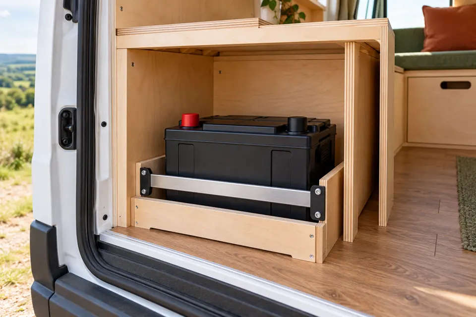
Use the instructions for the actual battery to settle its location, orientation, temperature limits, ventilation and clearances. A battery fitting inside a cupboard does not confirm that the cupboard is suitable. Different chemistries and products have different requirements.
Think about the complete physical job: carrying the battery into place, securing it, protecting the terminals and removing it later. Check the support and vehicle attachment for its mass and the intended installation loads.
Keep the planned space protected from water, loose metal objects and stored belongings. Do not use a service compartment as an unplanned general storage box.
Discuss cold-weather charging, any required temperature sensing or heating, and compatibility with every charger. Do not assume that a battery-management system makes all charging conditions acceptable. Keep the battery manual with the installation records.
Ask the installer to confirm the route between the battery and other high-current equipment before finalising the furniture. A layout that creates an awkward long run may need reconsidering. Do not move equipment contrary to its mounting or ventilation instructions merely to shorten a cable.
3. Lay out the equipment before fixing the board
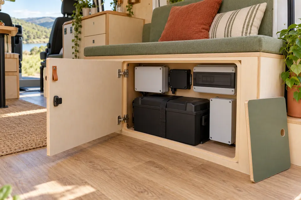
Make cardboard footprints from the actual product dimensions and trial them in the proposed service area. Include terminal access, connector space, cable bends, covers and the room needed to remove a component—not just its front face.
Follow each product’s mounting requirements for orientation, substrate and cooling. Confirm the mounting board and its attachment as part of the installation. A row of identical-looking boxes in a photograph is not a reason to copy their positions.
Keep required controls, isolation and protection reachable with the rest of the furniture in place. Try opening the cupboard with the bed made up and the normal storage loaded.
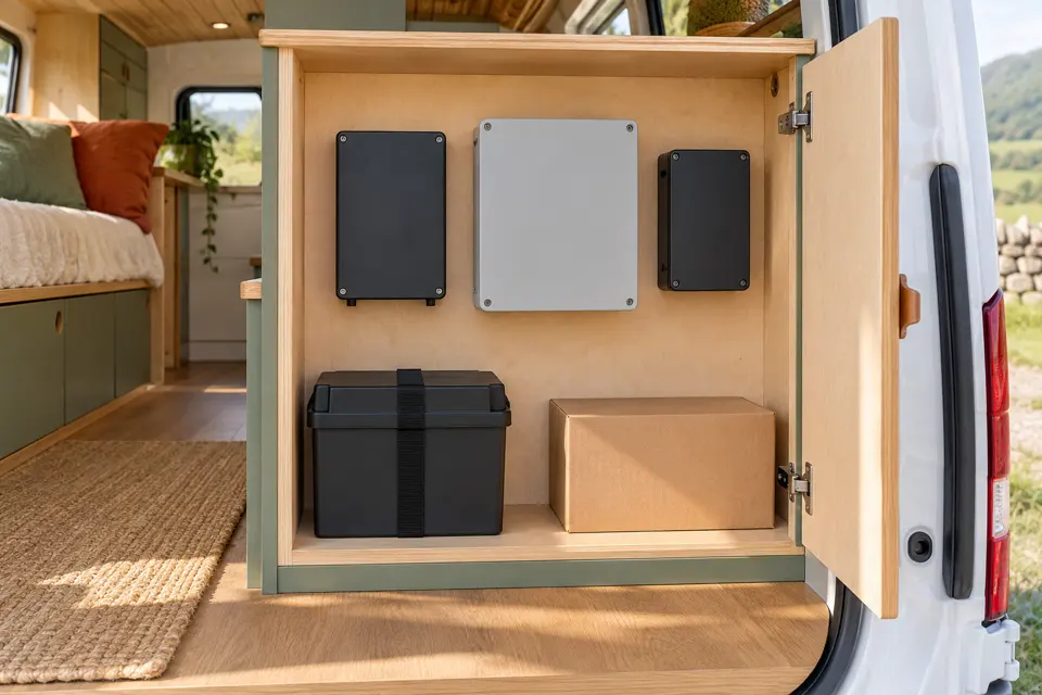
Allow the installer to review the proposed arrangement before drilling or cutting the final panels. Ask what must stay removable, which surfaces must be kept clear and what labelling needs to remain visible.
If changing a selected product, recheck its whole installation envelope. A cheaper replacement may have different terminals, cooling, settings or protection needs even if it performs the same broad role.
4. Plan routes around the finished build
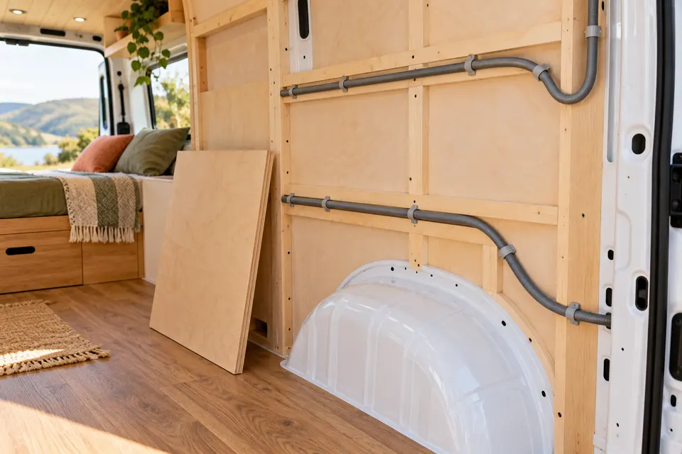
Sketch each route from the service area to its intended destination. Show the real path around openings, furniture and body features. Give the installer route lengths and access constraints rather than only straight-line distances.
Agree the permitted routes and containment for the circuits. Keep them clear of moving doors, drawer runners, sharp edges, hot equipment and planned furniture fixings. Do not create a route through an unknown vehicle cavity simply because it looks convenient.
Identify the places where a panel must come off later. A removable route can be more useful than a hidden short cut that cannot be inspected or replaced.
Record proposed mains, DC, data and sensor routes distinctly. Have their separation and enclosure requirements settled in the actual design; do not bundle everything into one sleeve because it looks tidy. The installer should account for the effect of grouping, insulation and containment on the selected cable.
Leave controlled service allowance where specified so equipment can be connected or removed without strain. Avoid loose coils and unsupported runs. Any spare route for future equipment should also be agreed; an empty conduit does not reserve electrical capacity.
Protect the cable, not just its appearance
Check every place a route passes through metal or furniture. Use an appropriate edge-protection or gland arrangement, with support and strain relief suited to the cable and location. A cable should not rub on a sharp edge or hang by its electrical connection.
Use the vehicle’s conversion guidance to establish permitted penetrations. Inspect behind and beneath before drilling. Protect newly exposed metal and seal weather-exposed penetrations using a suitable specified method.
Do not enclose a cable in conduit or bury it in insulation without the designer accounting for that installation method. Protective sleeving does not automatically make an undersized or overheating cable acceptable.
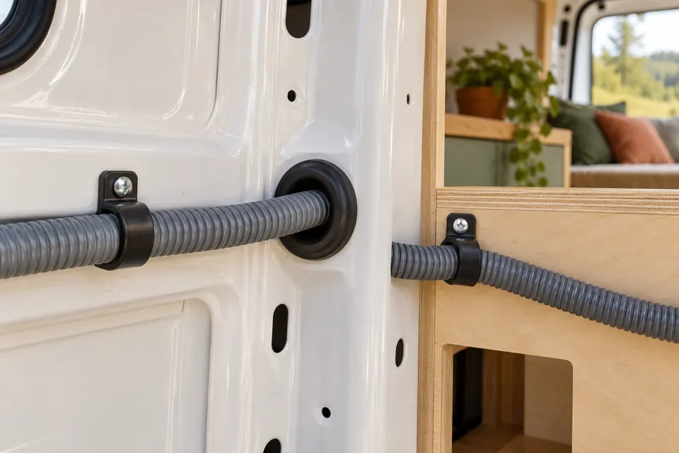
Agree the cable type, conductor size, circuit protection and connection method for each circuit before purchasing it. Jacket diameter alone does not tell you the copper cross-section. A generic online chart or calculator is not a complete vehicle installation design.
Have terminations made and checked using the method, tools and torque required by the actual components. Avoid unrecorded joins hidden behind permanent lining. Any repair or change needs appropriate inspection before the circuit is energised again.
5. Try socket, switch and light positions

Use small cardboard rectangles for proposed controls and outlets. Sit at the table, lie in bed and stand at the kitchen to check the reach. Include the depth of the fitting, back box and plug or connector, not just the faceplate.
Plan where a charging lead will lie. Keep it away from doorways, hot cooking areas, water and places where it will be trapped by a moving seat or drawer. Check the intended electrical fittings are suitable for their location.
Try the lights as a lighting plan too: reading, cooking, general light and a gentle night-time route can need different positions or switching.
Confirm the model of each outlet and light before final holes. USB charging points differ in output and capability; a port that charges a phone may not meet a laptop’s requirements. Give the installer the intended devices and product details.
Place necessary operating controls where you can identify and reach them, while protecting them against accidental use. Keep sockets and switches out of unsuitable wet or heat-exposed positions according to the actual installation design.
6. Plan how the energy gets back in
Tell the designer how you expect to recharge: driving, solar and optional mains hook-up. Decide which are essential and which can come later. Each added source needs compatible equipment, protection, controls and an agreed route.
For vehicle charging, use the conversion information for the actual van and alternator arrangement. Do not assume that a generic split-charge kit is appropriate for every generation of vehicle or battery.
For solar, plan the roof together with fans, rooflights, racks and service access. Confirm the panel/controller combination, mounting and weatherproof cable entry with the installer before making openings.

Panel wattage alone does not establish controller compatibility. The array’s electrical limits and expected conditions need checking against the actual controller instructions. Do not copy a series/parallel arrangement from a picture of another van.
For mains hook-up, agree the inlet position, cable route, distribution and protection as part of a complete mobile installation. An off-grid-focused build can still include hook-up if useful; it is your choice, with its own design and checks.
Understand protection and isolation before using the system
Have the designer specify the circuit protection and isolation for the actual sources, cables and equipment. A fuse rating is not something to increase because it keeps blowing. Stop using a circuit with a recurring fault and have the cause investigated.
Agree a clear user procedure for shutting down and making the system safe. A battery switch may not remove energy from solar, hook-up, an inverter/charger, another battery or retained charge in equipment. Turning off a light or seeing a blank display does not establish safe isolation.
For any mains or inverter AC installation, have earthing, protective devices and supply changeover designed and tested together. The correct arrangement depends on the actual equipment and operating modes. Do not add or remove neutral/earth links from general internet advice. An RCD test button is a user check, not proof of the complete installation.
Ask for the isolation instructions, circuit identification and any normal user checks in writing at handover. You should know what to do if something becomes hot, smells unusual, is damaged or repeatedly trips—stop use and obtain competent help.
7. Photograph and label before covering
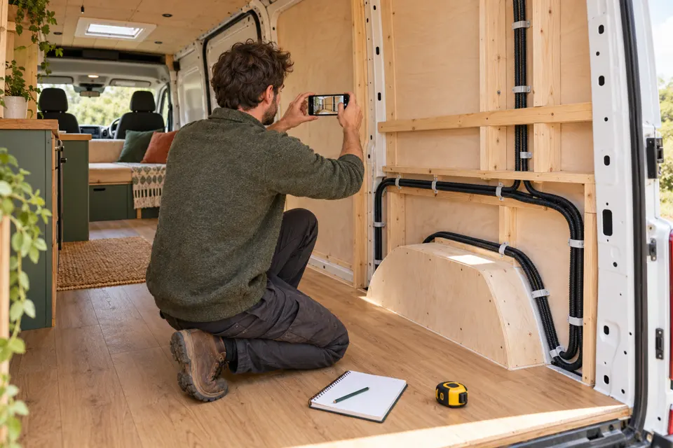
Take clear photographs before closing panels. Include fixed reference points such as door or window edges and record the route measurements separately. Keep images of backing and no-drill areas as well as electrical routes.
Use the circuit identification agreed with the installer. Keep it consistent between the design, labels and handover records. Labels should remain readable and appropriate to their location.
Keep actual product models, manuals, settings records and inspection documents together. A receipt proves purchase, not suitability or installation checks.
Record changes as the build develops. If you move a socket or change the appliance, tell the designer before extending a cable or replacing protection. Recheck the hidden route before any later drilling; photographs are useful records, not a guarantee of what is behind a surface.
8. Preserve access after the furniture goes in
Try removing the intended covers with the kitchen, bed and normal stored items in position. Can a person reach the component and use the required tools? Can a battery or charger be removed without dismantling unrelated services?
Keep specified ventilation and service space clear. Do not turn a carefully planned compartment into a tightly packed bedding store. Protect equipment against dropped objects, spilled water and accidental contact.
Make removable panels repeatable and secure for travel. Keep the intended access fixings visible or clearly recorded; avoid permanently bonding decorative trim over them.
Agree the work and checks with the installer
Before first fix, agree who supplies the design, chooses the equipment, installs the routes and cables, makes connections and completes inspection/testing. Make the scope clear if you want to do preparation yourself: have the installer approve it before you hide it.
- Give them the actual vehicle details and intended appliances.
- Agree the system diagram and circuit schedule for your build.
- Confirm cable/protection selection, permitted routes and mounting requirements.
- Agree the inspection point before lining or furniture closes access.
- Have all relevant supply modes and protection arrangements checked before use.
- Obtain the installation/test records appropriate to the work, plus clear user instructions.
Use someone competent in the actual vehicle systems involved. A familiarity with domestic sockets alone does not establish experience with leisure batteries, vehicle charging, solar and inverter supplies. Ask about those parts when discussing the job.
The website’s setup review can help highlight missing choices or recognised-product mismatches. It does not inspect your wiring, certify protection, approve PV strings or replace commissioning.
Time, preparation tools and a realistic allowance
For planning, a notebook, tape measure, cardboard, pencil, masking tape and a camera are enough to get started. Do not buy a reel of cable or a terminal kit before the design identifies what is needed. Specialist connection and test tools should suit the work and the installer’s method.
| Preparation allowance | Illustrative amount |
|---|---|
| Specified route protection, clips and glands | £40–£120 |
| Mounting/access materials and basic covers | £40–£100 |
| Identification and incidental consumables | £15–£40 |
| Example preparation total | £95–£260 |
These are editorial planning allowances, not supplier quotations or a complete electrical-system price. They exclude cables, fuses and distribution equipment, battery, chargers, solar, inverter, sockets, lights, design, labour and testing. Ask for an itemised quote for those once the requirements are known.
Keep preparation already included with a purchased kit or installation quote out of any second allowance. Record cabling, sockets and lighting in the existing build categories and equipment in its appropriate allowance. Reading this guide does not alter saved selections, prices or spending.
Book the first-fix inspection before fitting permanent panels. Allow time for the installer to review your mock-ups and for any changes to equipment or furniture. Keeping a removable access route can be worth more than rushing to finish the lining.
Common mistakes worth avoiding
- Buying cable by appearance. Use the specified conductor size and cable type.
- Choosing protection after the wiring. Design them together for the actual circuit.
- Copying a branded-kit picture. Similar-looking equipment can have different requirements.
- Hiding routes too early. Agree and complete the necessary checks before closing panels.
- Forgetting the return path or another source. Have the complete system designed, including protection and isolation.
- Using conduit as proof of safety. It does not establish cable capacity, segregation or correct terminations.
- Leaving no removal space. Trial access with the finished furniture and mattress in place.
- Assuming “off” means isolated. Follow the written procedure covering every relevant source.
Before closing the panels
- The intended loads and exact selected products are recorded.
- A competent installer has agreed the design, cable/protection selection and work scope.
- Battery location, restraint and product-specific conditions are accounted for.
- Equipment mounting, cooling, covers and removal space are planned.
- Routes avoid moving parts, heat, water exposure and furniture-fixing areas.
- Penetrations and route protection follow the specified vehicle/installation method.
- Socket, switch and light positions have been tried with the planned furniture.
- Charging sources, isolation and any AC supply arrangement are included in the design.
- Required first-fix checks are complete before concealment.
- Routes, fixed reference measurements and circuit identification are documented.
- Service access and user instructions are planned for handover.
This checkpoint is a preparation list, not electrical certification. Keep the system unenergised until the required installation and commissioning work is complete.
Instructions and further reading
Original CamperSteps writing and illustrations. The workflow is general planning guidance; the actual installation needs current vehicle, component and applicable installation requirements. No picture on this page is a circuit diagram.
- Ford Pro: vehicle-conversion resources—obtain the appropriate guidance for your own vehicle.
- Victron Wiring Unlimited: DC wiring, and earthing and electrical safety—technical background for the designer, not universal connection instructions.
- Victron: example solar-controller installation requirements—check the exact controller and array.
- Renogy: example battery installation manual—battery requirements are product-specific.
- Blue Sea Systems: limitations of wire/protection calculators—a marine calculator is not a vehicle-design approval.
Source information checked 2 November 2026. Costs are editorial allowances, not catalogue price updates. Reading this guide does not change a saved plan or certify its installation.
← Seating, cushions and upholsteryNext: Water supply and plumbing →