
Stage 3 · Plan the roof before you cover it
Solar panels, roof preparation and battery charging
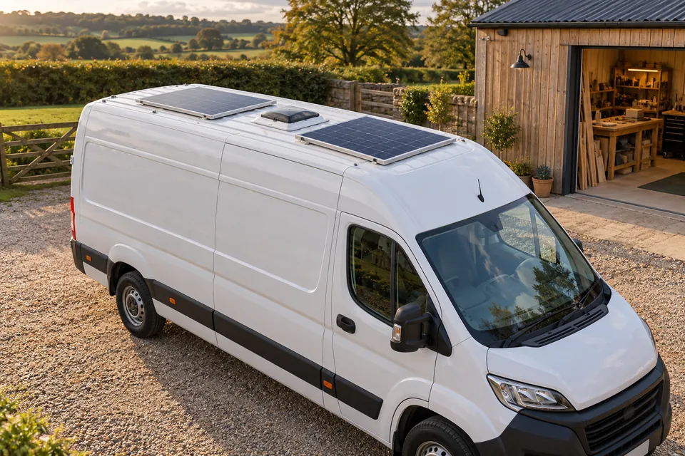
Plan your solar panels while the roof is still accessible from inside. Settle the panel footprint, approved mount positions and cable entry before insulation and ceiling lining hide the details. The final charging connections can follow later, when the battery and electrical system are ready.
Download solar and charging diagrams (PDF)
1. Treat the roof as an early conversion job
The best time to decide where roof equipment goes is before the ceiling becomes a finished surface. You can still see ribs, existing cables and potential service routes, and you can inspect the inside of an intended opening.
Plan solar alongside rooflights, fans, windows, racks and any aerials. One apparently convenient panel position can block a fan lid, shade another panel or put the cable entry where an overhead cupboard later prevents access.
That does not mean connecting every electrical item now. A useful early milestone is an agreed roof layout, properly completed roof attachments and entry work, and protected routes prepared for later wiring. Keep any unused entry or partly completed work weatherproof and managed according to the chosen system's instructions.
Record which jobs are ready and which are still provisional. Avoid drilling a hole “for later” before you know the panel, mount, entry fitting and route that will use it. Moving a roof hole is much harder than moving a cardboard template.
2. Measure the actual equipment

Use the selected panel's actual outside length, width, thickness and weight. Panels with the same advertised wattage can have different dimensions. Check the physical product and its current drawing rather than borrowing a measurement from another make.
Include the mounting feet or rails, cable exit, junction box and the access needed to secure and maintain the panel. The glass rectangle alone is not the complete installation footprint.
Make a cardboard template if it helps. Mark the front of the van and the proposed panel orientation. Keep any cut or fixing marks clearly provisional until checked against the actual mounting instructions.
Measure the usable roof area, not the vehicle's overall catalogue length and width. Roof curvature, ridges and edge details reduce the area suitable for a particular mount. Record dimensions in the downloadable sheet without treating its blank grid as a scale drawing.
Include the mass of panels, supports and other roof equipment when checking vehicle payload and the permitted roof arrangement. Roof load limits and mounting capability are vehicle-specific; a larger panel is not automatically the most useful choice.
3. Plan the whole roof on one sketch
Draw the rooflight or fan in its fully open position as well as closed. Add racks, awnings, aerials and any planned equipment. Leave the manufacturer's required room for panel ventilation, drainage, fixings and service access.
Look for shade from raised equipment, especially when the sun is low. Move the paper rectangles around before buying. A layout with more nominal watts may perform less usefully if important parts are regularly shaded.
Think about the inside route at the same time. An entry near the controller may reduce routing complexity, but it still needs an appropriate roof location and a protected, maintainable path through the van.
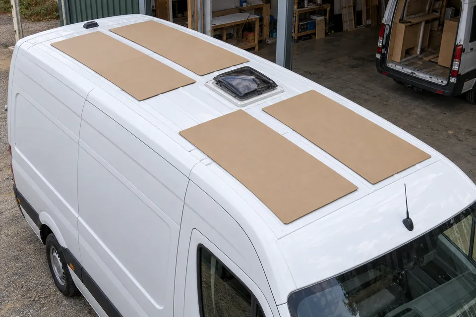
Plan safe access to the job. Do not assume the thin roof skin can support a person, and do not use a convenient tyre or open door as a work platform. Arrange suitable access equipment and help for handling panels; stop if wind or weather makes the work unsuitable.
A roof plan is also a chance to leave future options. You might reserve a route for an additional panel without buying it now, provided the current installation is complete, sealed and safe in its own right. Do not leave loose connectors or unsealed penetrations as a future provision.
4. Settle the mounting method before drilling
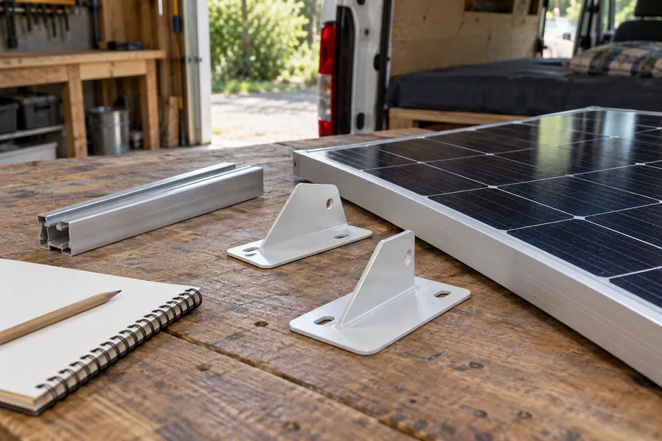
Panel mounts need to withstand the loads of a moving vehicle, including wind and vibration. Select a system approved for the actual panel, roof material and vehicle use. A bracket sold for a building roof is not automatically a suitable van solution.
Mechanical fixings, factory mounting points, rails and bonded feet have different requirements. Confirm where loads are carried, what support is needed underneath and whether the vehicle guidance permits the proposed attachment.
For bonded mounts, the adhesive name alone is not a design. Roof coating condition, bracket material, preparation, bond geometry and cure conditions all matter. Obtain the mounting supplier's approved procedure and any adhesive manufacturer's required advice or testing.
A bead that has formed a skin is not necessarily ready to carry road loads. For example, Sika's Sikaflex-554 data sheet describes a professional-use bonding product and calls for testing with the actual materials and conditions. That is not blanket permission to glue any bracket to any painted roof.
For mechanical attachment, use the specified hardware, support, corrosion isolation and sealing arrangement. Do not invent a universal screw count or substitute a larger screw when the support is unsuitable. Do not drill new panel-frame holes unless the panel manufacturer explicitly permits them.
Keep the mount instructions, approved panel clamping or fixing locations and any required inspection record. If the products or roof do not have a confirmed compatible method, resolve that before cutting or bonding.
5. Check both sides of every proposed hole
Inspect the intended location from outside and inside while the van is still open. Identify structural ribs, existing wiring, pipes, seams and restricted drilling areas. Use the conversion/body guidance for the exact vehicle generation and roof.
Do not drill through a roof rib or another structural member simply because it aligns with a bracket. A different layout or approved mounting system may be needed. If you cannot identify what is behind the position, stop and establish it before proceeding.
Once the location and method are confirmed, use the selected fitting's actual template and specified hole dimensions. Protect the interior from swarf, manage drill penetration and use the appropriate tools and access arrangement for that job.
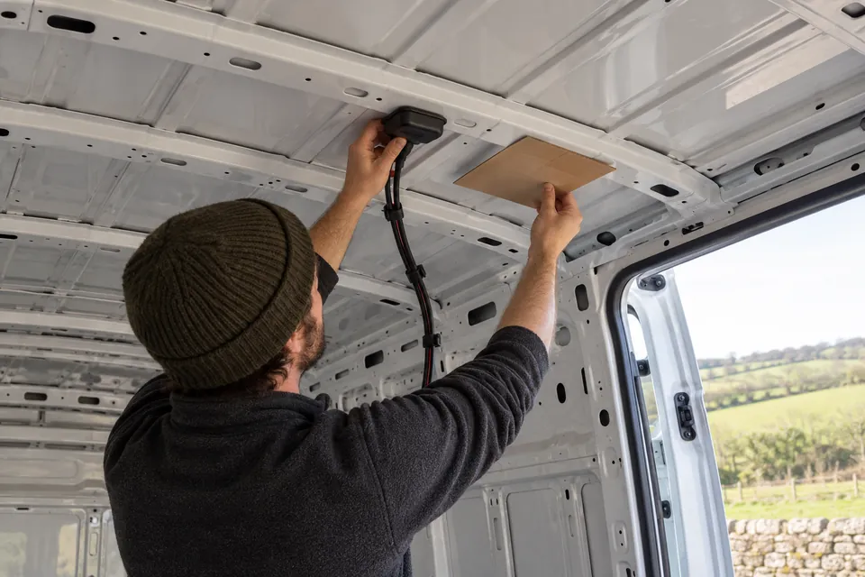
Collect metal debris rather than leaving it in roof channels or on the paint. Finish cut edges, restore corrosion protection and seal penetrations according to the vehicle and fitting instructions. Sealant does not replace structural support or the specified protection of bare metal.
Check the completed work for weatherproofing using the appropriate procedure before covering the inside. Photograph the roof entry, fixings and support arrangement. Leave any serviceable connection or fastening accessible rather than burying it permanently behind lining.
6. Plan the cable entry and the inside route
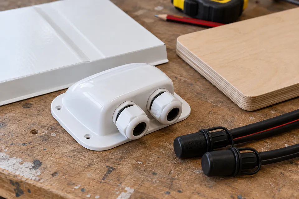
Choose an entry fitting suitable for the actual roof, cable diameters and exposure. Check how its base seals against the roof shape and how the cables are supported. A gland's sealing range matters; tightening it around the wrong cable is not a dependable solution.
Protect cables from sharp edges, rubbing, water paths and moving equipment. Leave the manufacturer's required bend radius and strain relief. Avoid a route where the panel frame or another roof component can pinch the cable.
Use compatible solar connectors and the specified cable/termination method. Similar-looking connectors are not automatically a compatible pair. Do not separate PV connectors under load or use them as a substitute for suitable isolation.
Plan the route to a dry, accessible controller location with its required ventilation and mounting surface. Identify it in your route photographs before lining. Leave enough access to service the entry and connections without removing unrelated furniture.
Solar panels can produce voltage whenever lit, even before the battery is connected. Keep handling, connection and isolation under the equipment's specified procedure. Switching off a leisure-battery switch alone does not establish that solar wiring is dead.
7. Understand panels → controller → battery
The panel makes electrical energy from light. The solar charge controller manages the charging output for a compatible battery. The leisure battery stores energy for use when the available solar is lower than demand.
A panel should not be connected straight to a leisure battery. Use a compatible controller and the required protection, isolation and wiring. The controller's PV input and battery output are different connections, even if the terminals look similar.
Match panel voltage and current to the controller's limits, including cold-weather open-circuit voltage. A controller's battery-charge current rating alone does not tell you whether a particular panel arrangement is permitted.
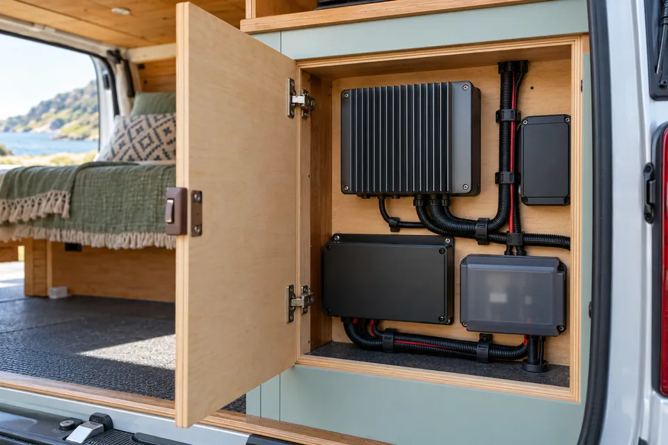
Series connections add panel voltage; parallel connections add available current for matched arrangements. Which is suitable depends on the panels, shading, wiring and controller. Do not choose from a generic “two panels” diagram without checking actual Voc, current and temperature data.
For a product-specific example, Victron's SmartSolar 100/30 and 100/50 installation manual gives its own PV limits and connection procedure. It calls for establishing the battery connection and recognised system voltage before PV in the normal automatic-detection sequence. Follow the current manual for your controller; do not transfer that sequence or its ratings to unrelated equipment.
Solar nameplate watts are test-condition ratings, not a promise of energy every day. Season, shade, orientation and weather matter. Keep the battery and recharging plan tied to ordinary use, with a fallback for periods of poor solar.
8. Add driving charge with the right vehicle interface
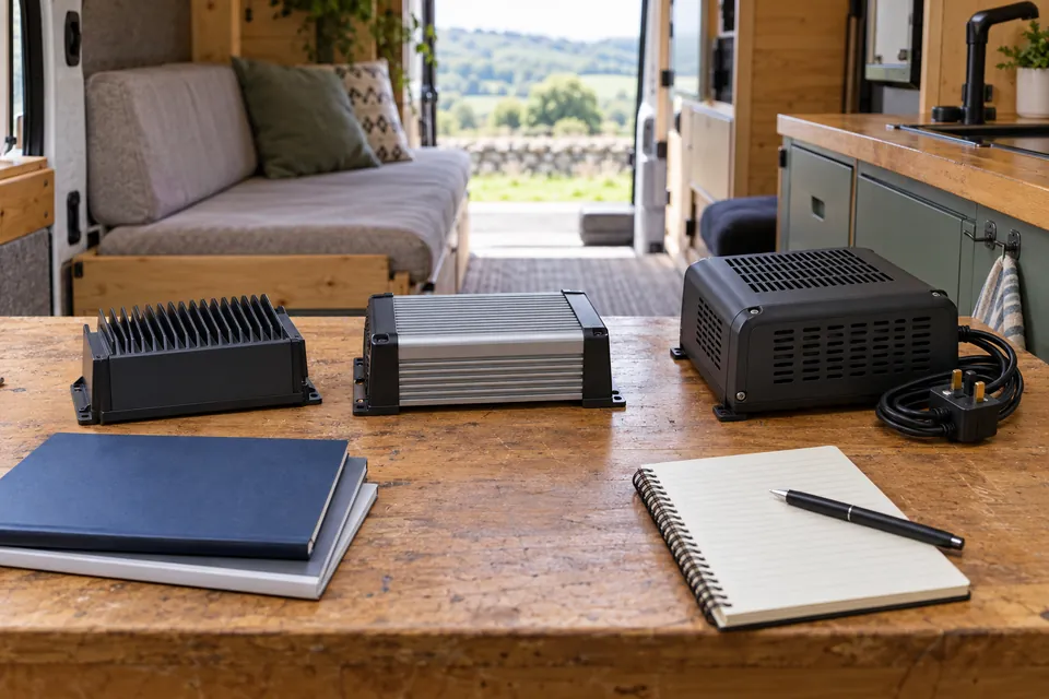
Driving charge is a separate route from the vehicle's approved electrical connection to a suitable leisure-battery charger. A DC-DC charger can control that charging process when the chosen vehicle and battery require it.
Check the actual alternator arrangement, permitted connection point, available capacity and vehicle conversion instructions. A simple split-charge relay is not automatically appropriate for a smart alternator or a lithium battery.
Set the charger current and engine-running control for the vehicle and battery. Do not assume its maximum rating is the correct continuous demand for every alternator or operating condition.
The two ends of this route can each have an energy source, so the cable and protection design must account for both sides. Use the chosen charger's instructions and a complete circuit schedule, not only a fuse near one battery.
Keep starter and leisure functions properly managed so ordinary camping use does not unexpectedly flatten the starter battery. Do not bypass the intended controls to force charging. A combined solar/DC-DC unit may simplify the equipment count, but its shared limits and operating behaviour still need checking.
9. Optional hook-up charging is another separate source
If you choose to use mains hook-up, a suitable AC battery charger can recharge the leisure battery from that supply. It does not replace the solar controller or create an inverter supply for household appliances when away from hook-up.
Choose the correct input-voltage model and a battery-compatible charging profile. The hook-up inlet, AC protection, earthing, distribution and verification form their own installation and need competent leisure-vehicle design and testing.
Do not feed an inverter output back into the hook-up inlet or improvise connections between AC sources. If you want an inverter, charger/inverter or source switching, include it explicitly in the design. The downloadable energy map shows the optional mains charging route, not mains wiring instructions.
10. Bring the sources together at the leisure system
Solar, driving and mains charging can all serve one compatible leisure-battery system when correctly designed. Their outputs do not normally pass through one another in a chain. Each needs the appropriate connection, protection and control arrangement.
The battery, its BMS and the wiring must accept the maximum combined charging current that can occur. Matching the voltage labels is not enough. Agree charge settings, temperature limits, sensing and any BMS-controlled stop signals for every source.
Provide suitable positive and negative connection arrangements. Covered distribution equipment can make the system easier to understand and service. If a shunt monitor is used, its connections must follow its manual so charging and load currents are measured correctly.
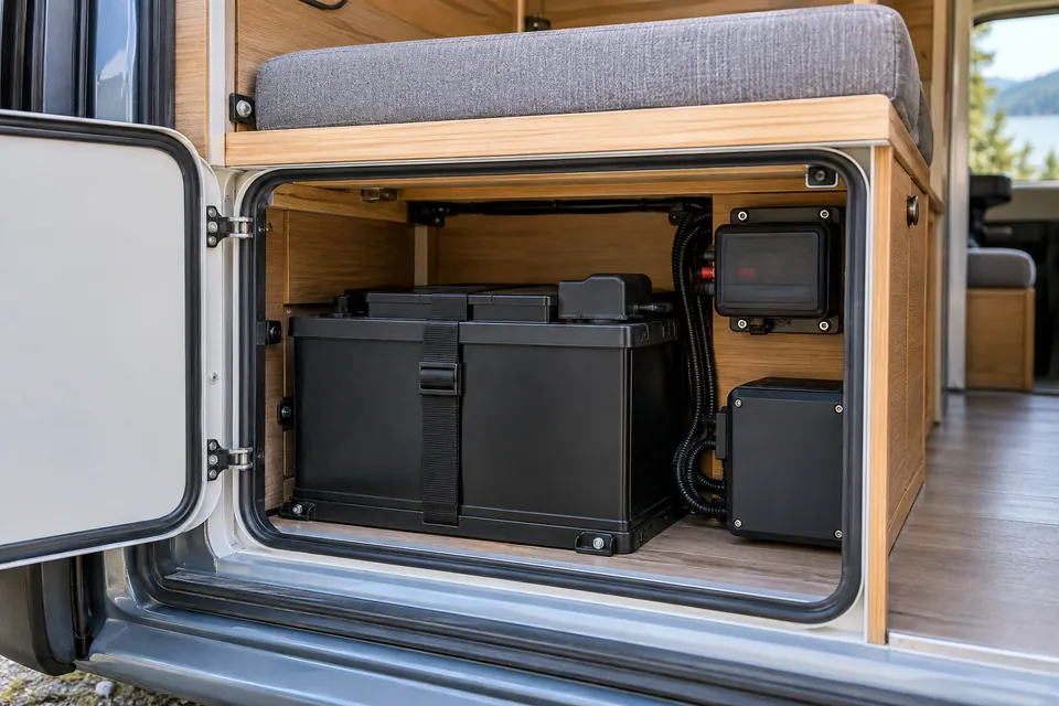
Route leisure loads through the appropriate protected distribution circuits. Lights and a water pump are different from a high-current inverter branch. Do not use a small fuse board or a controller's load terminal beyond its actual permitted capability.
Make sure a system shutdown deals with every source and any stored energy. The final instructions should identify what remains live and how isolation is verified before maintenance. Labels and a clear handover are part of a useful installation.
Download the system diagrams and worksheets
The six-page PDF gives you a roof sketch sheet, a solar-to-battery connection map, a three-source charging overview, a typical 12 V load branch, a product/circuit schedule and a handover checklist. Print it or keep it with your build documents.
The maps explain how the parts relate. They leave product ratings and cable/fuse selections to the actual design rather than inventing values for an unknown van. Negative paths, controls, earthing/bonding and isolation need the detail appropriate to your equipment; the overview arrows do not represent a complete set of individual wires.
Download solar and charging diagrams (PDF)
This is a normal PDF document, separate from the JSON file used to save and restore your personal build. The worksheet does not change any saved plan, equipment selection or price.
11. Make the final connections to the agreed design
Finish the mechanical support, guarded terminals, protected cable routes and component mounting before the system is energised. Have the installer check the equipment identities, conductor schedule, protection and polarity against the final drawing.
Use the connection order, terminal torque, settings and commissioning procedure for the actual products. Record the selected battery chemistry, charge limits and temperature controls. A generic internet diagram is not authority to bypass those instructions.
Verify each source on its own and in the combinations intended by the design. Confirm charging behaves correctly with the engine running and stopped, in available sunlight and on optional hook-up. Battery current can differ from a charger's output because leisure loads may be consuming some of that energy.
Investigate faults, unexpected heating, damaged connectors or protection operating. Do not increase a fuse rating to make a fault disappear. Keep the results and appropriate installation verification with the finished wiring drawing.
12. Keep a record you can use later

Save photographs before insulation hides the roof entry and routes. Record the panel and mount models, products used, work date and any preparation or cure requirements. Keep an inspection routine for fasteners, bond condition, roof seals and cable support as specified by their manufacturers.
Check the system after the initial trips and at the intervals set by the installer and product guidance. Address water ingress, movement, cable rubbing or damaged protection promptly. Do not climb onto the roof for a casual inspection without a suitable access arrangement.
Solar output will vary. Before deciding the system is faulty, compare the conditions, battery state and active loads with the expected behaviour. Use the actual controller's diagnostics rather than assuming an app's power figure is the day's stored energy.
Your two-stage checklist
| Before insulation and ceiling lining | Before electrical handover |
|---|---|
| Actual panel and mounting footprint checked | PV limits, battery and all charger models confirmed |
| Rooflight opening and other equipment allowed for | Complete cable, fuse and isolation schedule agreed |
| Vehicle-approved attachment and entry locations settled | Every source uses compatible charging settings and controls |
| Corrosion protection and sealing completed and checked | Correct product-specific connection and commissioning procedure completed |
| Protected route and service access recorded in photographs | Final drawing, labels and shutdown/maintenance instructions supplied |
Budget for the whole job: panels, compatible mounts, entry fittings, appropriate preparation/sealing products, protected cable routes, controller, circuit protection, battery and any driving or mains charger. Include access equipment, design and fitting/testing work where required. A cheap panel price is not a complete charging-system price.
Instructions used for this guide
This is original CamperSteps content. Consult the exact van's body/conversion guidance and the current panel, mounting and entry-fitting manuals. Technical references include Sika's caravan and motorhome application information and Sikaflex-554's product data sheet; SmartSolar MPPT installation instructions; Orion XS DC-DC instructions; and Wiring Unlimited's DC wiring guidance. Examples explain the checks; they do not select a complete system for your van.
Later in the build, use electrics and cable routing for equipment access and hidden routes, and lighting and sockets for everyday positions.